GC³ Technical Manual: Cooling Water
Introduction
Most industrial production processes need cooling water to operate efficiently and safely. Refineries, steel mills, petrochemical manufacturing plants, electric utilities and paper mills all rely heavily on equipment or processes that require efficient temperature control. Cooling water systems control these temperatures by transferring heat from hot process fluids into cooling water. As this happens, the cooling water itself gets hot; before it can be used again it must either be cooled or replaced by a fresh supply of cool water. This makeup water contains dissolved minerals, suspended solids, debris, bacteria and other impurities. As the water continues to circulate throughout the system, other contaminants begin to concentrate. As the temperature rises, cooling equipment efficiency is threatened and a total plant shutdown can result.
Effective cooling water operation and treatment can prevent such an occurrence. After completing this chapter, you will have a basic understanding of the different types of cooling water systems now used, their mechanical components, and the problems associated with cooling water. In-depth methods for control of these problems (scale, corrosion and fouling) appear in greater detail in other chapters. Basically, this chapter will help you to become familiar with the many terms and concepts common in the water treatment industry.

Types of Cooling Water Systems
Cooling water systems are either nonevaporative or evaporative. Nonevaporative systems include once-through cooling and closed loop systems. Evaporative cooling systems include open recirculating systems in which heat rejection is accomplished in cooling towers, evaporative condensers, spray ponds or cooling lakes. Technically, large cooling lakes (1500-3000 acres) fall into the evaporative category, but the evaporation may be so minimal that it is offset by environmental moisture (dew, rainfall, runoff, etc.). In that case, a cooling lake will have problems and solutions similar to those of a once-through system.
Once-Through Cooling
Once-through cooling water is used to cool processes or equipment and then is discharged to waste. Characteristically, it involves large volumes of water and small increases in water temperature. Because there is no opportunity for evaporation, there is virtually no increase in dissolved or suspended solids. Once-through cooling is usually employed when water is readily available in large volume at low cost. Common sources are rivers, lakes and wells, where the only cost involved is that of pumping.
Once-through cooling is currently prevalent in utilities, steel mills and paper mills. Scale, corrosion, waterborne fouling and biological fouling are all problems for once-through cooling systems (Figure 11.1).
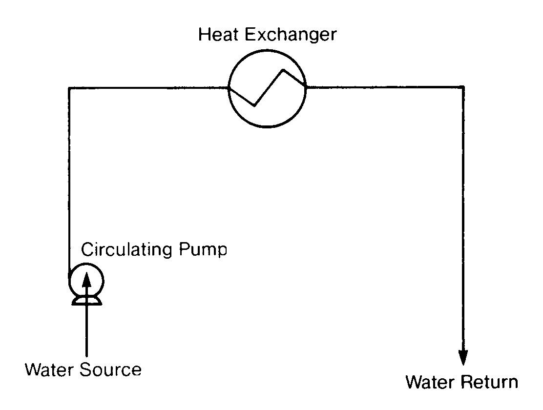
Closed Cooling
A closed cooling water system is a recirculating water system that does not cool by evaporation and has very little water loss. Daily water losses from leakage range from 0.5% to 5% of system volume. Fresh makeup water is needed only to replace these uncontrollable losses.
Figure 11.2
Closed Cooling System
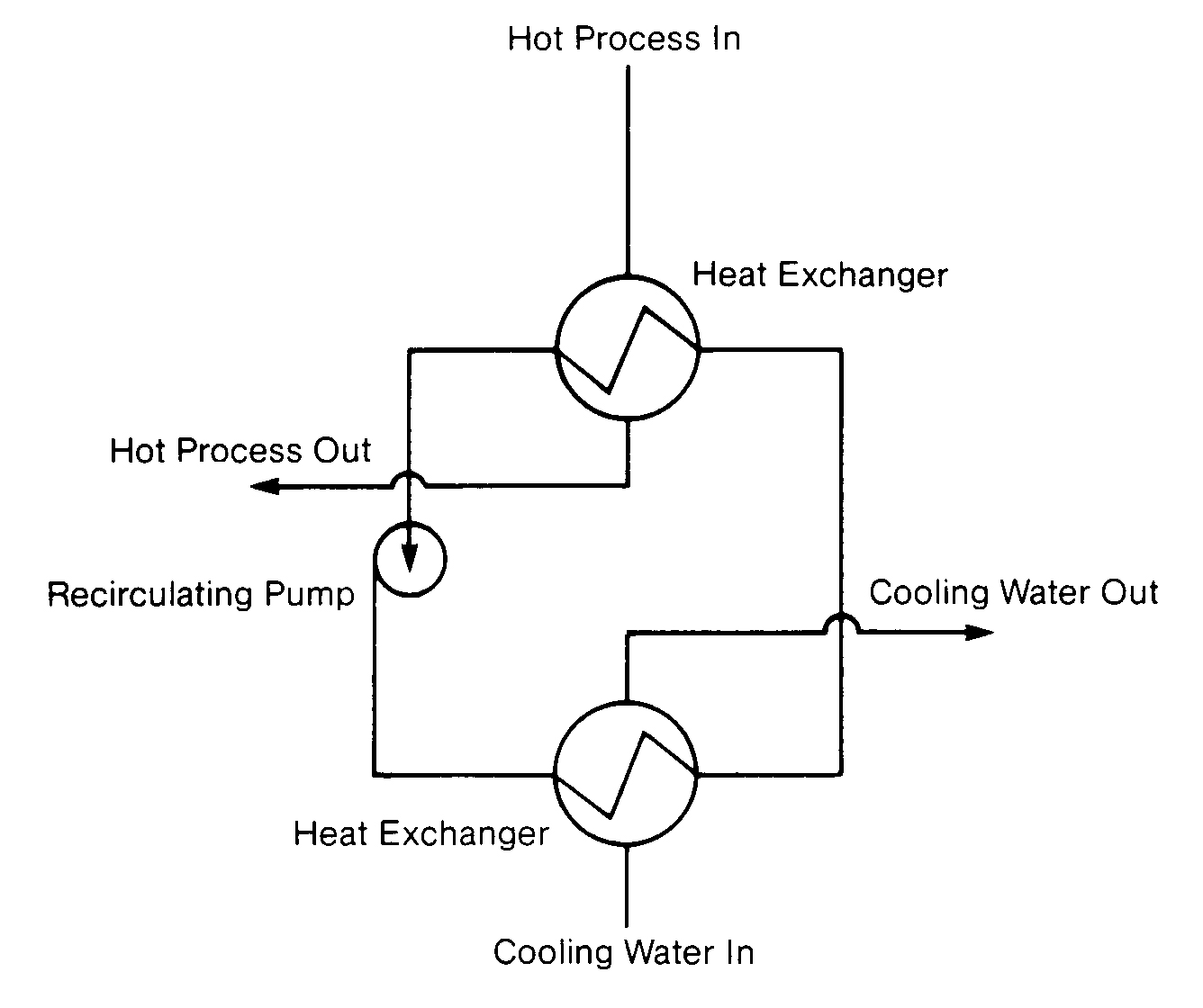
Closed systems offer the advantages of precise temperature control, which is critical in many process applications, and low treatment cost. Closed systems can be reliably operated at very high temperatures (200 º F [93 ºC] and 200 psig) and under sub-freezing conditions using ethylene glycol, alcohol or brines (Figure 11.2).
Because a secondary cooling system and heat exchanger(s) are needed to cool the closed system. higher capital and operating costs are disadvantages of this design. The fresh makeup to closed systems usually needs to be sodium zeolite softened or demineralized.
Open Recirculating Cooling Towers
As recently as 20 years ago, cooling towers were more the exception than the rule in the industry because of their severely high operating cost and the large amount of capital required for construction. But with today's need for water conservation and minimal environmental impact. industry is turning more and more to recycling water.
A cooling tower is a heat exchanger: it transfers heat from circulating water to the atmosphere. It accomplishes this by providing intimate mixing of water and air, which results in cooling primarily by evaporating approximately 1 % of the flow for each 10 ºF drop in temperature. This section provides an introduction of cooling tower designs.
Function
Cooling usually takes place both by evaporation and sensible heat loss. Approximately 1000 Btu are lost for every pound of water evaporated. The amount of heat lost by the water depends on the temperature rise of the ambient air before it leaves the tower. This means that both the dry bulb and wet bulb temperatures of the air are important.
The wet bulb temperature of the air is the lowest temperature at which water can be cooled by evaporation. The wet bulb temperature is also the dew point of the ambient air. It is not practical to design a cooling tower to develop a sump temperature equal to the wet bulb. The difference between the sump temperature and wet bulb is referred to as the approach. Typically it is 10-30ºF. but it can run higher in some processes. Because heat rejection
is accomplished primarily by evaporation of a portion of the cooling water, towers are designed to optimize intimate air/water contact.
Types of Towers
Cooling towers may be classified as either natural draft or mechanical draft. The natural draft or hyperbolic cooling tower is designed to take advantage of the temperature differences between the ambient air and the hotter air inside the tower. The design creates a chimney effect that causes the cold air at the bottom of the tower to push the warmer air out the top.
FIGURE 11.3
Natural Draft Cooling Towers (Crossflow and Counterflow)
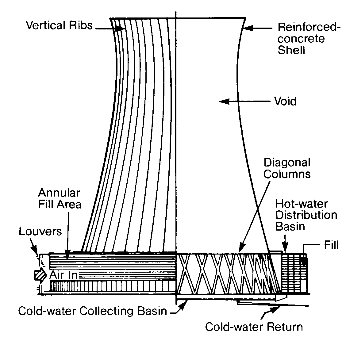
Hyperbolic towers are divided into two basic types: crossflow (Figure 11.3, left) and counterflow (Figure 11.3, right). In a crossflow tower, air is drawn across the falling water. In this design the fill is located outside the tower. The fill is contained within a counterflow tower since the air is drawn up and through the failing water. Design selection depends upon conditions at the particular site.
In the United States, natural draft towers are generally used only for large electric utility condenser cooling. Flows may be as high as 500,000 gpm. A 400-foot-high tower with no moving parts is capable of evaporating in excess of 10,000 gallons of water per minute.
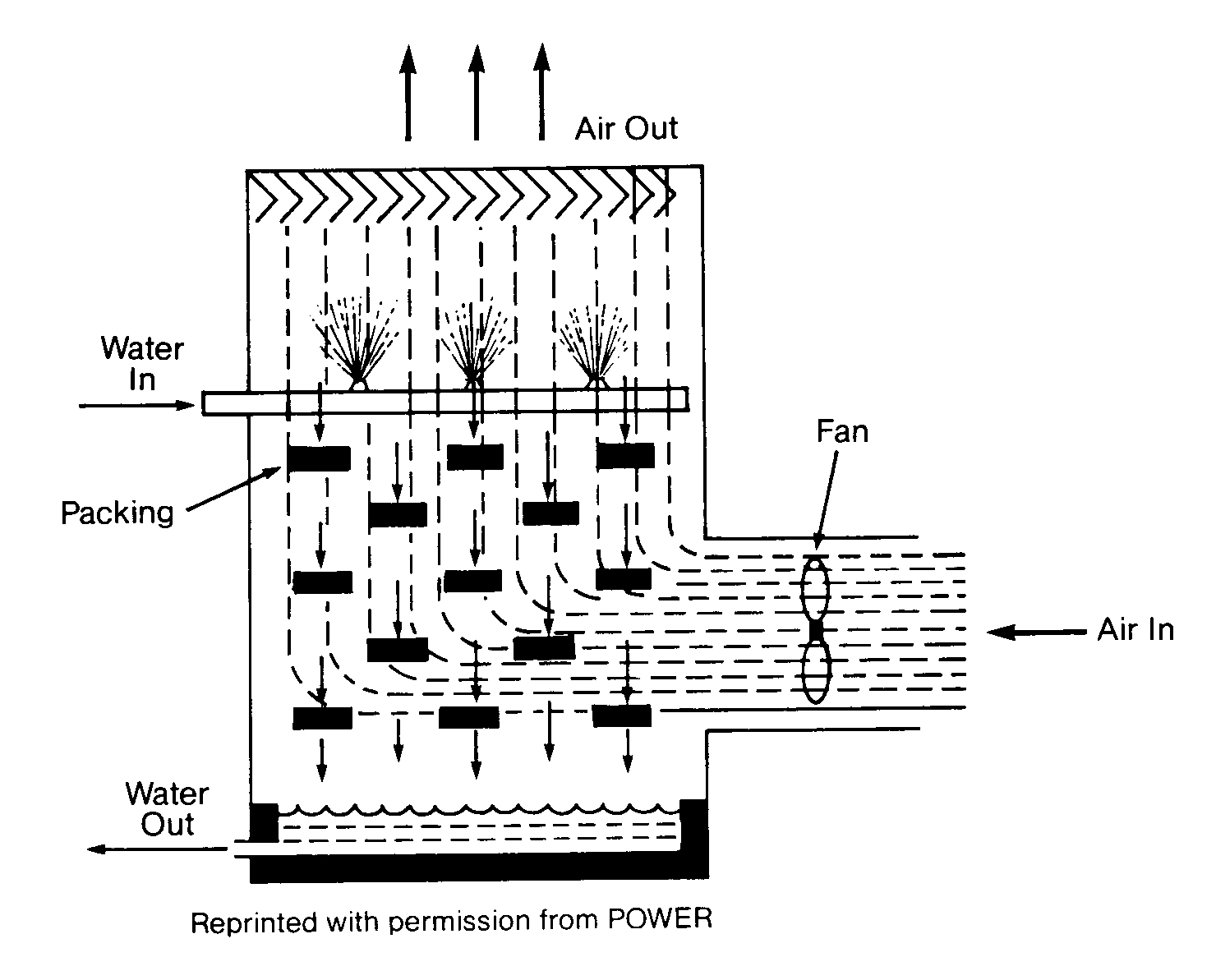
Figure I 1A shows the components of a typical mechanical draft cooling tower. Water is distributed as evenly as possible at the top of the tower and allowed to drop through the air. Fans are used to increase the air flow. Packing or fill inside the tower keeps the water evenly distributed and increases the water surface area. The greater the surface area. the greater the air contact and. therefore, the greater the cooling efficiency.
Mechanical draft towers are divided into two basic designs: forced draft or induced draft. They are easily distinguished because a forced draft tower (Figure 11. 5) has fans on the side, and an induced draft has fans on the top.
FIGURE 11.4
Mechanical Draft Tower

FIGURE 11.5
Forced Draft Tower
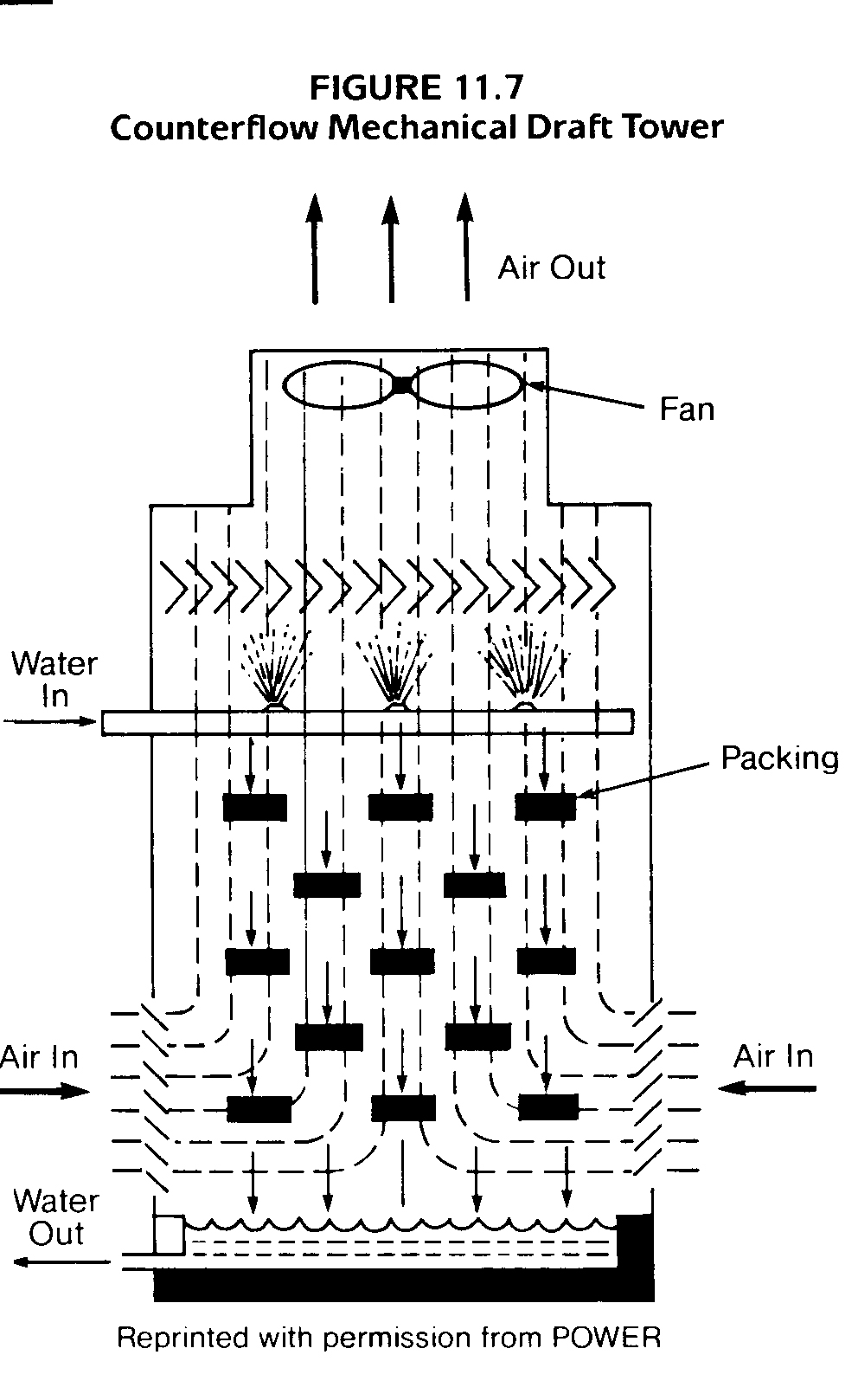
Induced draft towers are also divided into two basic designs: counterflow and crossflow. As in the natural draft towers, a crossflow tower (Figure 11.6) draws the air across the falling water droplets and out the stack. They are identifiable by their open decks and the louvers that go all the way from top to bottom of each tower cell. Counter flow mechanical , draft towers (Figure 11.7) are identified by their perpendicular side walls and closed decks.
Regardless of whether the air is pushed or pulled through the tower, and whether or not the air is fan-assisted, the principle, the problems, and the solutions are the same.
FIGURE 11.6
Crossflow Tower
Glossary of Cooling Tower Terms
Approach-The difference between cold water temperature (sump) and wet bulb temperature.
Cell-The smallest tower subdivision which can function independently with regard to air/water flow.
Cooling Range-The difference between the warm water temperature to the tower and the cold water temperature leaving the tower. Also referred to as the temperature drop across the tower (D T).
Dry Bulb-Ambient air temperature
Fill or Packing-The structural system which keeps the water evenly distributed as it falls through the tower.
Wet Bulb-The dew point of the air, which is also the coldest temperature to which water can be cooled by passing it through air. Wet bulb temperature is normally determined by using a psychrometer that contains a thermometer in contact with a water-wetted wick.
Problems in Cooling Water Systems
Raw or filtered makeup water contains dissolved minerals and insoluble matter that pose a serious threat to efficient cooling. Microbiological organisms, dirt or silt, dissolved minerals and gases, if left untreated, can concentrate and cause serious reductions in heat transfer efficiency, increased maintenance problems, or even a total system failure.
By their very design, open recirculating cooling systems are prime candidates for contamination problems. As the cooling water evaporates, contaminants are allowed to concentrate in the system. Contaminants enter the system either through the makeup water or from the air via the cooling tower. If left untreated, high concentrations of impurities in open recirculating systems can lead to a number of serious problems, including:
1. Scale
2. Fouling
3. Microbiological growth
4. Corrosion
While open recirculating systems are particularly vulnerable to these problems, once-through and closed systems are also subject to these same problems. All systems require attention to these four areas. More attention is given to open recirculating systems because of the greater potential for problems inherent in their design.
Scale
The most serious side effect of scale formation is reduced heat transfer efficiency. Loss of heat transfer efficiency can cause reduced production or higher fuel cost. If heat transfer falls below the critical level. the entire system may need to be shut down and cleaned. Unscheduled downtime can obviously cost thousands of dollars in lost production and increased maintenance. Once scale becomes a serious threat to efficiency or continued operation, mechanical or chemical cleaning is necessary.
In most cases, mineral scale is a silent thief of plant profitability. Even minute amounts of scale can provide enough insulation to affect heat transfer and profitability severely.
Scale in cooling water systems is mainly composed of inorganic mineral compounds such as calcium carbonate (which is most common), magnesium silicate, calcium phosphate and iron oxide. These minerals are dissolved in the water, but if left to concentrate uncontrolled, they will precipitate. Scale occurs first in heat transfer areas but can form even on supply piping. Many factors affect the formation of scale, such as the mineral concentration in the cooling water. water temperature, pH, availability of nucleation sites (the point of initial crystal formation) and the time allowed for scale formation to begin after nucleation occurs.
Dissolved mineral salts are inversely temperature soluble. The higher the temperature, the lower their solubility. The most critical factors for scale formation are pH, scaling ion concentration and temperature. Consequently, most open recirculating systems operate in a saturated state. because the scaling ions are highly concentrated. Precipitation is prevented under these conditions by the addition of a scale inhibitor. The mechanisms of scale formation. as well as their prevention and control, are discussed in greater depth in Chapter 2.
Fouling
Waterborne contaminants enter cooling systems from both external and internal sources. Though filtered and clarified, makeup water may still hold particles of silt. clay, sand and other substances. The cooling tower constantly scrubs dirt and dust from the air, adding more contaminants to the cooling water. Corrosion by-products, microbiological growth and process leaks all add to the waterborne fouling potential in a cooling system.
The solids agglomerate as they collide with each other in the water. As more and more solids adhere, the low water velocity, laminar flow, and rough metal surfaces within the heat exchangers allow the masses of solids to settle out, deposit onto the metal. and form deposits. These deposits reduce heat transfer efficiency, provide sites for
underdeposit corrosion, and threaten system reliability. Waterborne fouling can be controlled by a combination of mechanical and chemical programs
Microbiological Contamination
Cooling water systems are ideal spots for microscopic organisms to grow. "Bugs" thrive on water, energy and chemical nutrients that exist in various parts of most cooling water systems. Generally, a temperature range of 70-1 40 º F (21-60 oC) and a pH range of 6-9 provide the perfect environment for microbial growth. Bacteria, algae and fungi are the most common microbes that can cause serious damage to cooling water systems. Microbiological fouling can cause:
1. Energy losses
2. Reduced heat transfer efficiency
3. Increased corrosion and pitting
4. Loss of tower efficiency
5. Wood decay and loss of structural integrity of the cooling tower
Corrosion
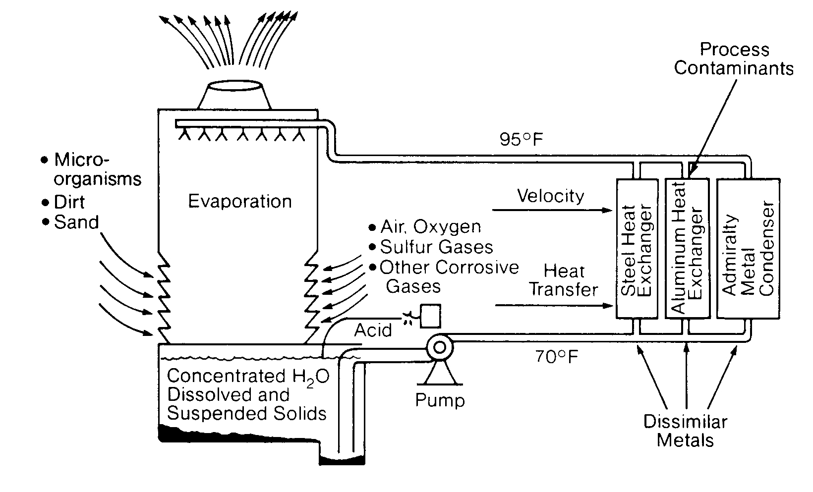
Corrosion is the breakdown of metal in the presence of water, air and other metals. The process reflects the natural tendency of most manufactured process metals to recombine with oxygen and return to their natural (oxide) states. Corrosion is a particularly serious problem in industrial cooling water systems because it can reduce cooling efficiency, increase operating costs, destroy equipment and products and ultimately threaten plant shutdown.
Most cooling systems are very vulnerable to corrosion. They contain a wide variety of metals and circulate warm water at relatively high linear velocities. Both of these factors accelerate the corrosion process. Deposits in the system caused by silt, dirt, debris, scale and bacteria, along with various gases, solids and other matter dissolved in the water all serve to compound the problem (Figure 11.8). Even a slight change in the cooling water pH level can cause a rapid increase in corrosion. Open recirculating systems are particularly corrosive because of their oxygen-enriched environment. Corrosion processes and methods of control are considered in Chapter 3.
Cooling Tower Material Balances
It is essential for you to be able to do a material balance for a cooling system in order to detect fouling or precipitation and to determine treatment chemical feed rates. Pure water vapor is lost from the systems by evaporation (E), leaving behind all of the solids present in the makeup (M) water. All the constituents in the makeup will be present in the recirculating (R) cooling water at some increased level of concentration, depending on the wastage (W) of recirculating water from the system. The cycles (X) of concentration are determined by dividing the makeup by the wastage (M/W).
D T Cooling range (D T) of a cooling tower is the difference between the entering and leaving temperatures.
R Recirculation (R) rate is the water flow over the tower in gallons per minute.
Btu British Thermal Unit (Btu) is the heat required to raise the temperature of one pound of water one º F.
H Heat load (H) is the heat absorbed by the cooling water system which must be rejected in the cooling tower expressed in Btu/min.
![]()
W Wastage (W) is the total water (in gpm) removed from the cooling water system. This is the sum of leakage, drift (D) and blowdown (B). Leakage is the unintentional loss of water, which in some cases can be as much as the evaporation (E). All values are expressed in gpm.
W = B + D + (leakage) L
L Leakage (L) is unknown and/or uncontrolled water losses.
B Blowdown (B) is the controlled discharge of recirculating water to waste that is necessary to limit the solids in the system.
D Drift (D) is the recirculating water entrained in the air flow discharged to the atmosphere. This is 0.01 -0.3% of the recirculation rate for a mechanical draft tower. The lower drift loss at 0.01 % is common for a modern tower
E Evaporation (E) takes heat away from the recirculating water in the water vapor that is produced. The latent heat of evaporation of 1000 Btu per pound of water evaporated generally accounts for 80-100% of the heat rejected by the cooling tower, with 20% or less being removed as sensible heat through air contact with hotter water.
E(gpm) = (0.001) (R) (D T)
This equation represents the maximum evaporation: it is the slide rule calculation.
E(gpm) = (0.8) (6301) (R) (D T)
The 0.8 is an approximation of the evaporation considering sensible heat rejection to the air.
M Makeup (M) to an open evaporative recirculating system is the sum of evaporation (E), blowdown (B), drift (D) and any leakage.
M = E + B + D + L
since W = B + D + L,
M = E + W
X The cycles of concentration (X) is the ratio of makeup (M) to wastage (W).
since M = E + W, then
Another way to express cycles of concentration (X) is the number of times makeup constituents are concentrated in the recirculating water, where:
CM is the concentration of ion in makeup, CW is the concentration of ion in wastage.
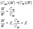
Care must be used to pick a constituent that is not affected by treatment chemicals or contaminants and that is also stable. Depending on the system, Cl, SO,4, Si02, Ca, or Mg might be considered. The ions added with makeup must equal those lost in the wastage.
Often, the mere presence of the word cycles is a source of confusion when discussing instructions about cycles of concentration. There is a tendency to believe this term has a direct relationship to the number of times the cooling water passes over the tower. It does not.
Makeup = water losses evaporation + blowdown + drift + leakage
Makeup = evaporation + wastage (B + D + L + W)
Evaporation = (0.001 ) (recirculation rate) (change in temperature)
Cooling Water Heat Exchangers
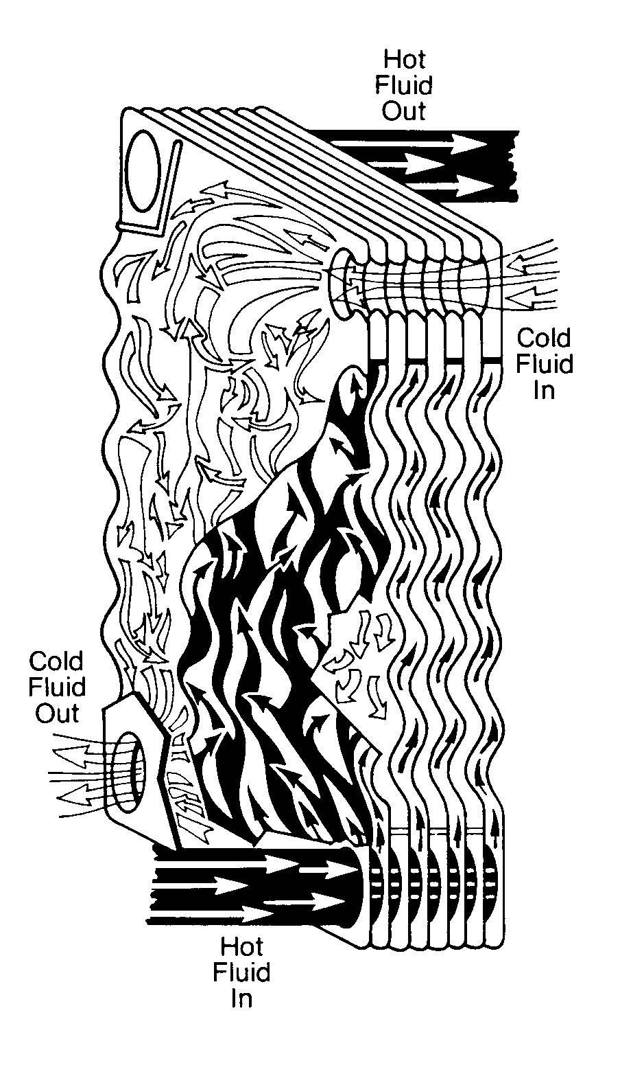
A heat exchanger is a device in which two fluids (or one vapor) flow against the opposite sides of a solid boundary wall that separates them while permitting heat to pass from the hot to the cold fluid. Of the various types of heat exchangers. the shell and tube type is the most widely used. It consists of a number of tubes enclosed in an outer circular shell. In Figure 11.10 you can see that one fluid flows inside the tubes and the other fluid flows outside them.
You will also notice that in this particular example cooling water is on the shell side. Shell-side cooling water exchangers characteristically are very low velocity (1 -3 ft/sec2) and high heat flux exchangers. Therefore, they are very prone to fouling and they must be watched closely.
![]()
FIGURE 11.9
Factors Used in Determining Cycles of Concentration
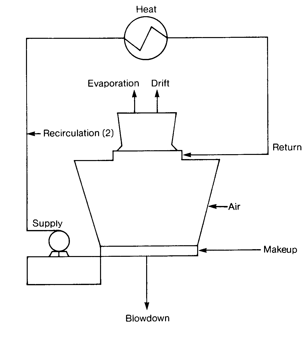
FIGURE 11. 10
Cooling Water Heat Exchanger
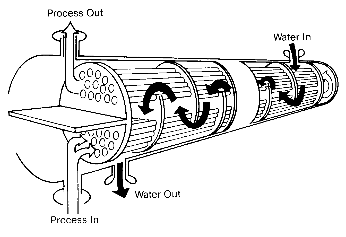
FIGURE 11. 11
Fixed Tubesheet Exchanger
FIGURE 11.12
Floating Head Removable Tubular Heat Exchanger
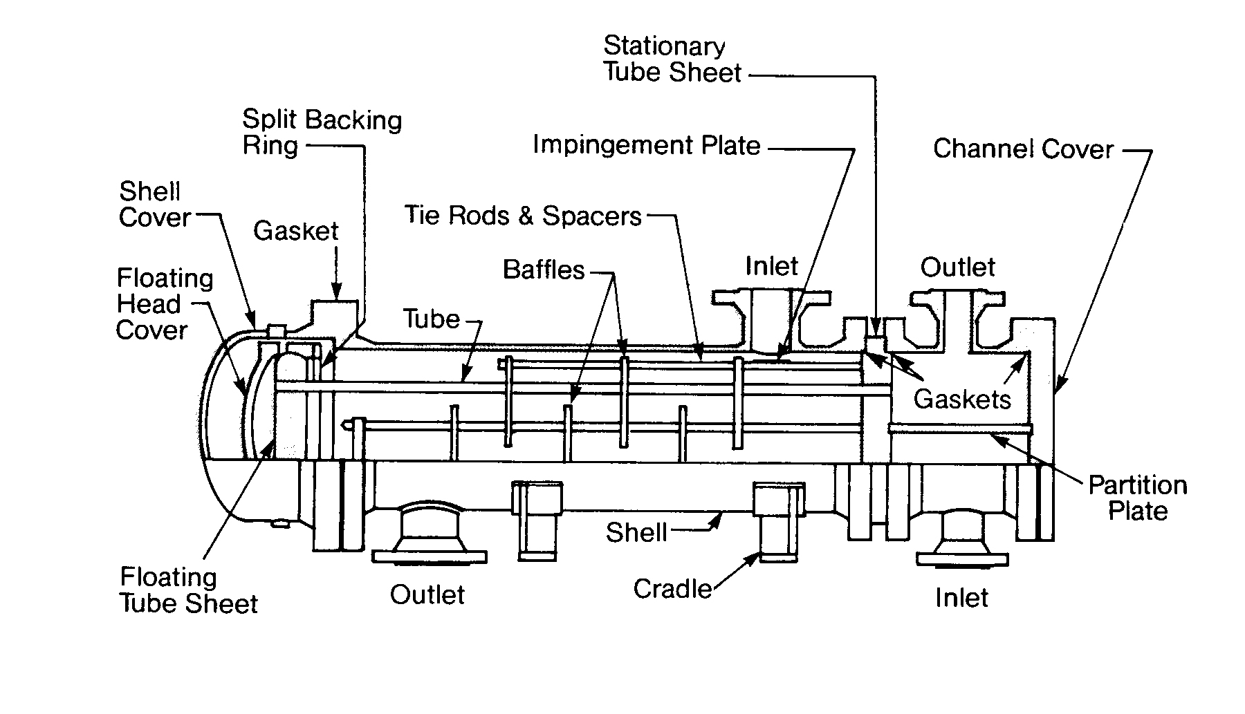
FIGURE 11.13
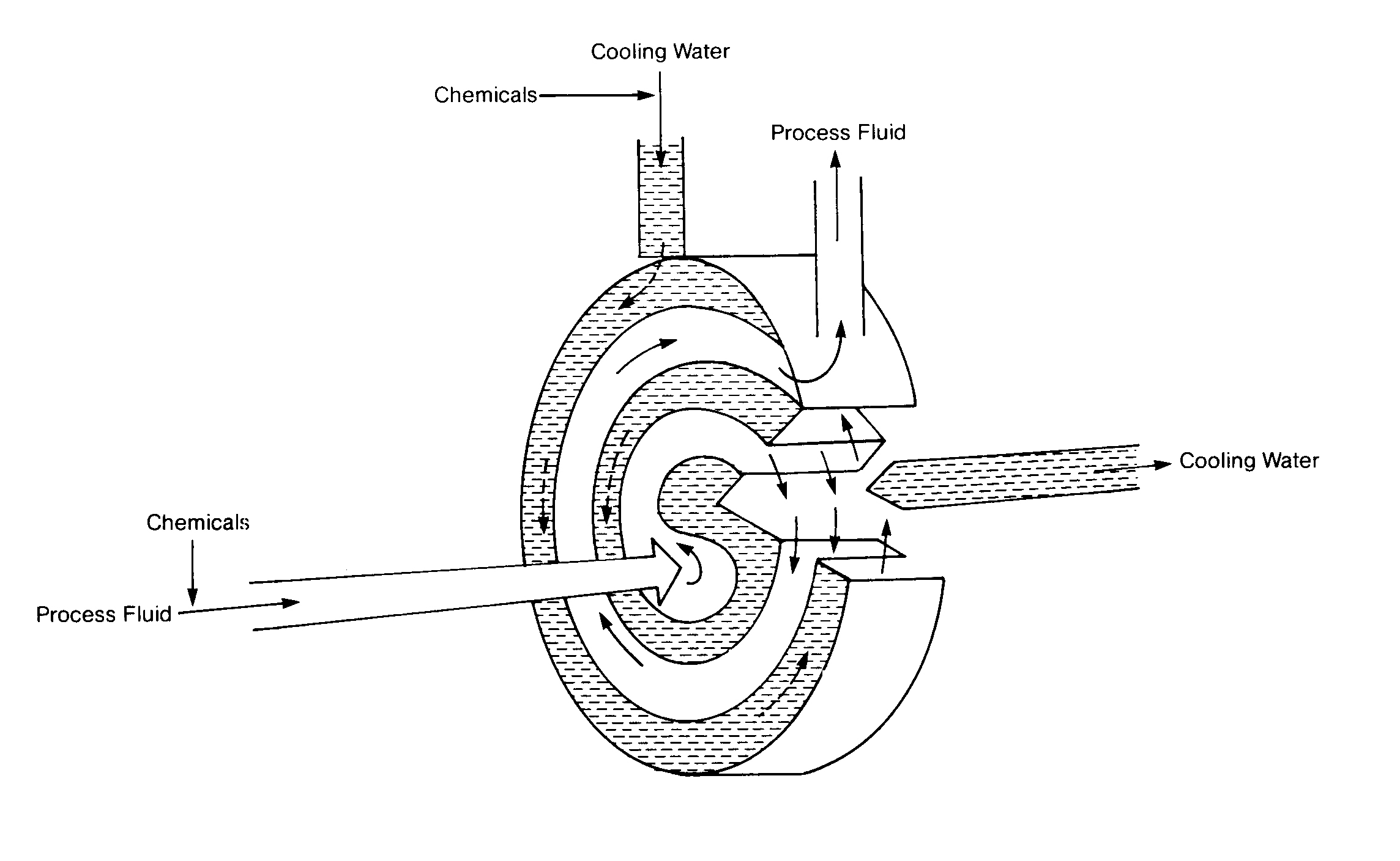
Spiral Heat Exchanger
Not all cooling water is used for heat exchanger duty. Cooling water in different industries may come into direct contact with the plant's products or equipment. In Figures 11. 1 4, 11.15 and 11. 16, cooling water is being used to cool a refractory to prolong the refractory life and to directly cool metal vessels that have molten metal inside. Otherwise, this structure would disintegrate and a catastrophic failure would result.
In steel and aluminum manufacturing, cooling water may be sprayed directly upon poured molten slabs, then recycled. Every industry has its own surprising uses for cooling water. There are as many uses for cooling water as there are types of exchangers.
FIGURE 11.14
Cooling Water System in an Electric Furnace
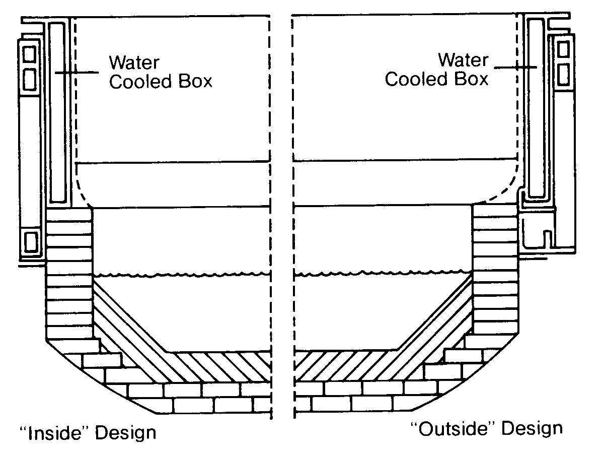
FIGURE 11. 15
Cooling Water System in a Grey-iron Foundry with Wet Scrubbers
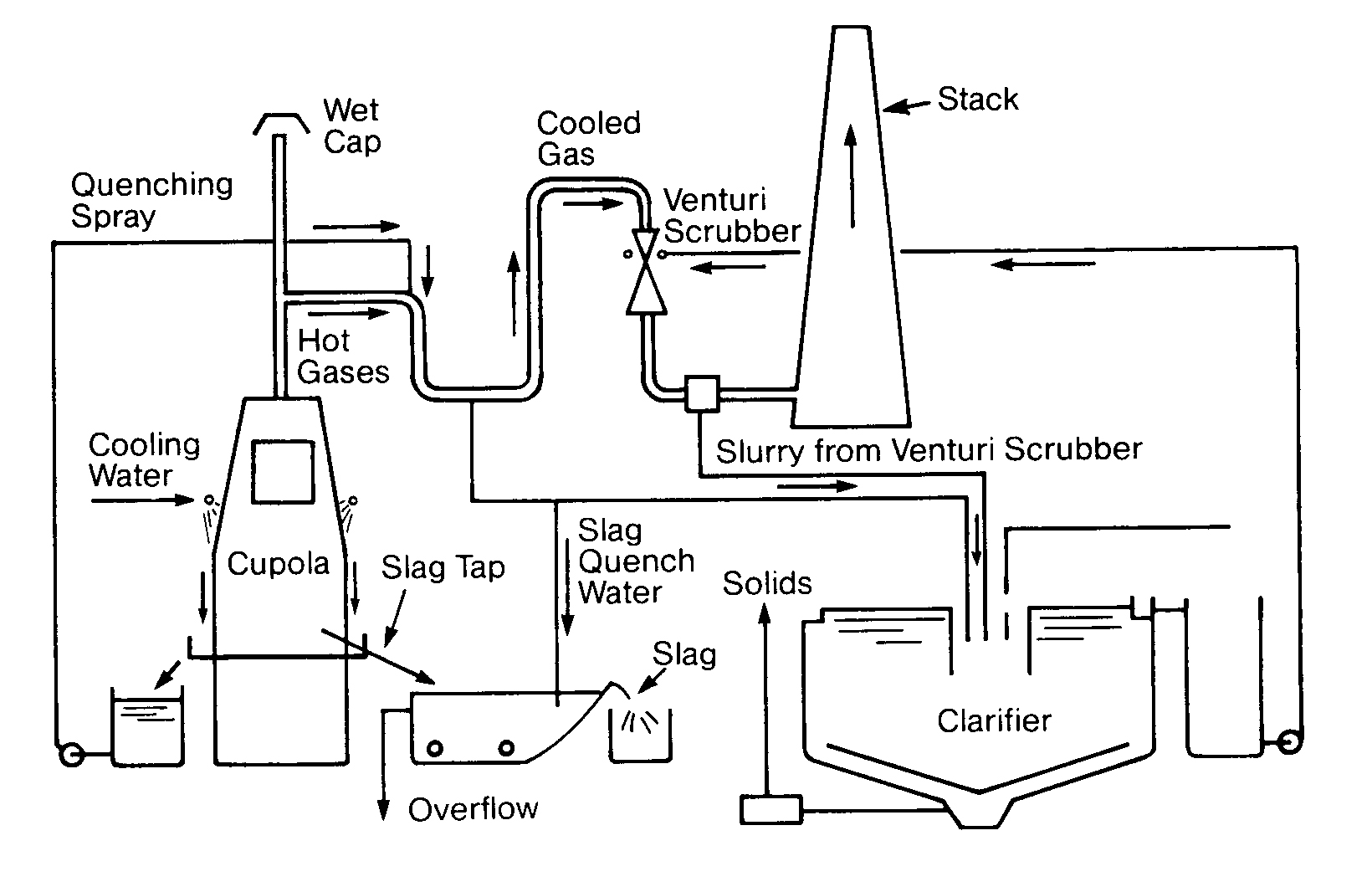
FIGURE 11.16
Two Cooling Water Systems in a Blast Furnace
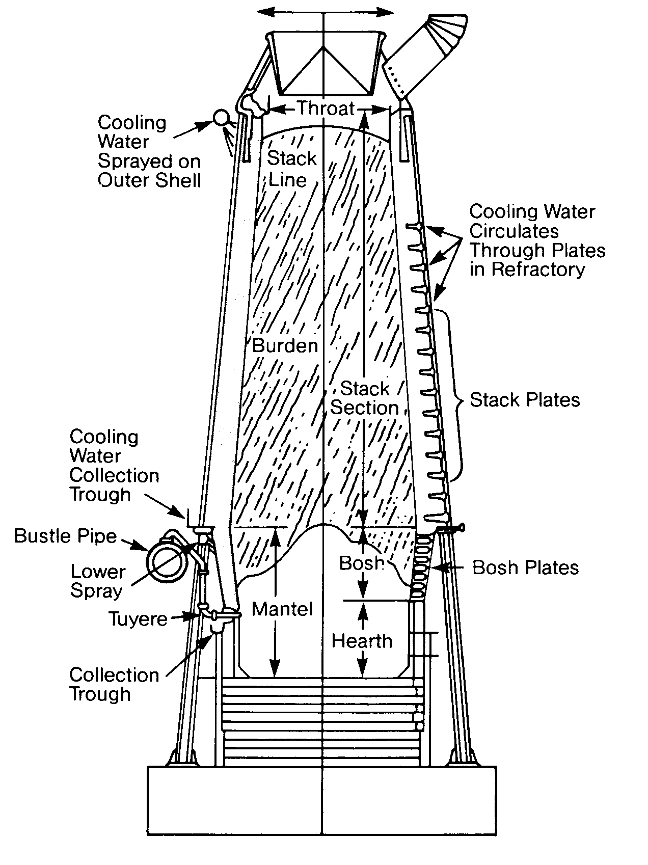
FIGURE 11.17
Plate Heat Exchanger